Custom Grippers & Teleop Tools
Two custom end-effectors designed for cloth manipulation: silicone FSR grippers for contact-aware grasping, and a UMI-inspired handheld teleoperation gripper with ArUco markers and IMU for imitation learning data collection.
Part 1: Force-Sensing Silicone Grippers
The default SO-101 grippers work fine on rigid objects. On fabric, they either slip or bunch the material. The fix: cast custom silicone fingertips with embedded FSR sensors so the gripper knows when it’s actually holding something.
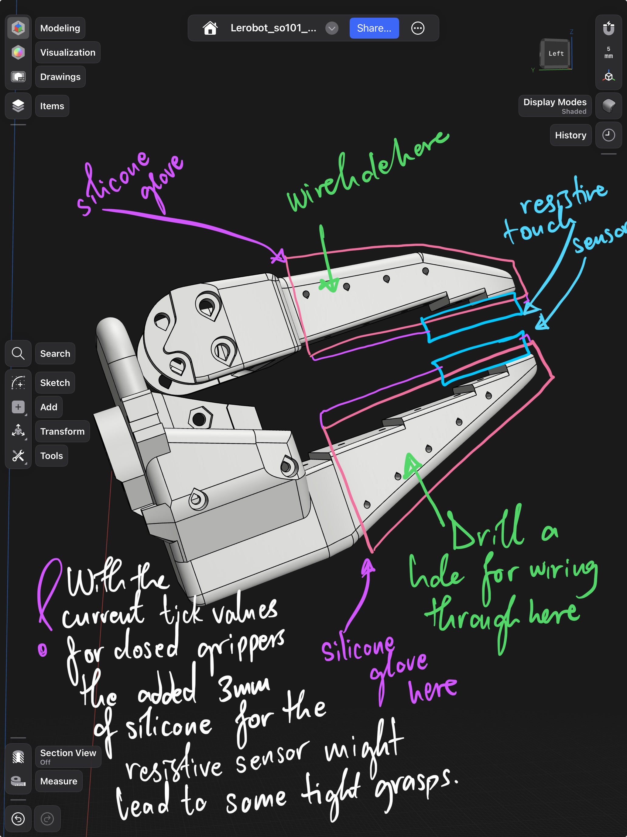
Design
- Moulds designed to cast silicone fingertips that conform to fabric surfaces
- FSR sensors embedded inside the silicone; signal feeds to controller to modulate grip pressure
- Silicone compliance gives a larger contact patch than rigid 3D-printed fingers
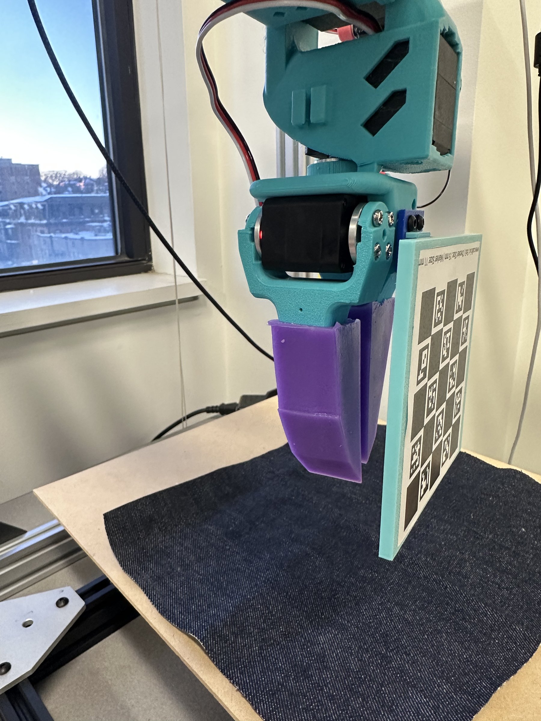
Grasp Comparison
Without FSR: Gripper closes to a fixed position. Works on some fabrics, slips on others, bunches delicate material.
With FSR: Closes until force threshold, then holds. Consistent grasp across fabric weights and thicknesses, from silk to denim.
Degassing silicone matters more than you think. Trapped air bubbles create weak spots right where the FSR sits. A vacuum chamber before curing made a big difference in sensor reliability.
FSR placement is a balancing act. Too deep in the silicone and the signal is damped to uselessness. Too shallow and it pokes through after a few hundred grasps.
Part 2: UMI-Inspired Teleop Gripper
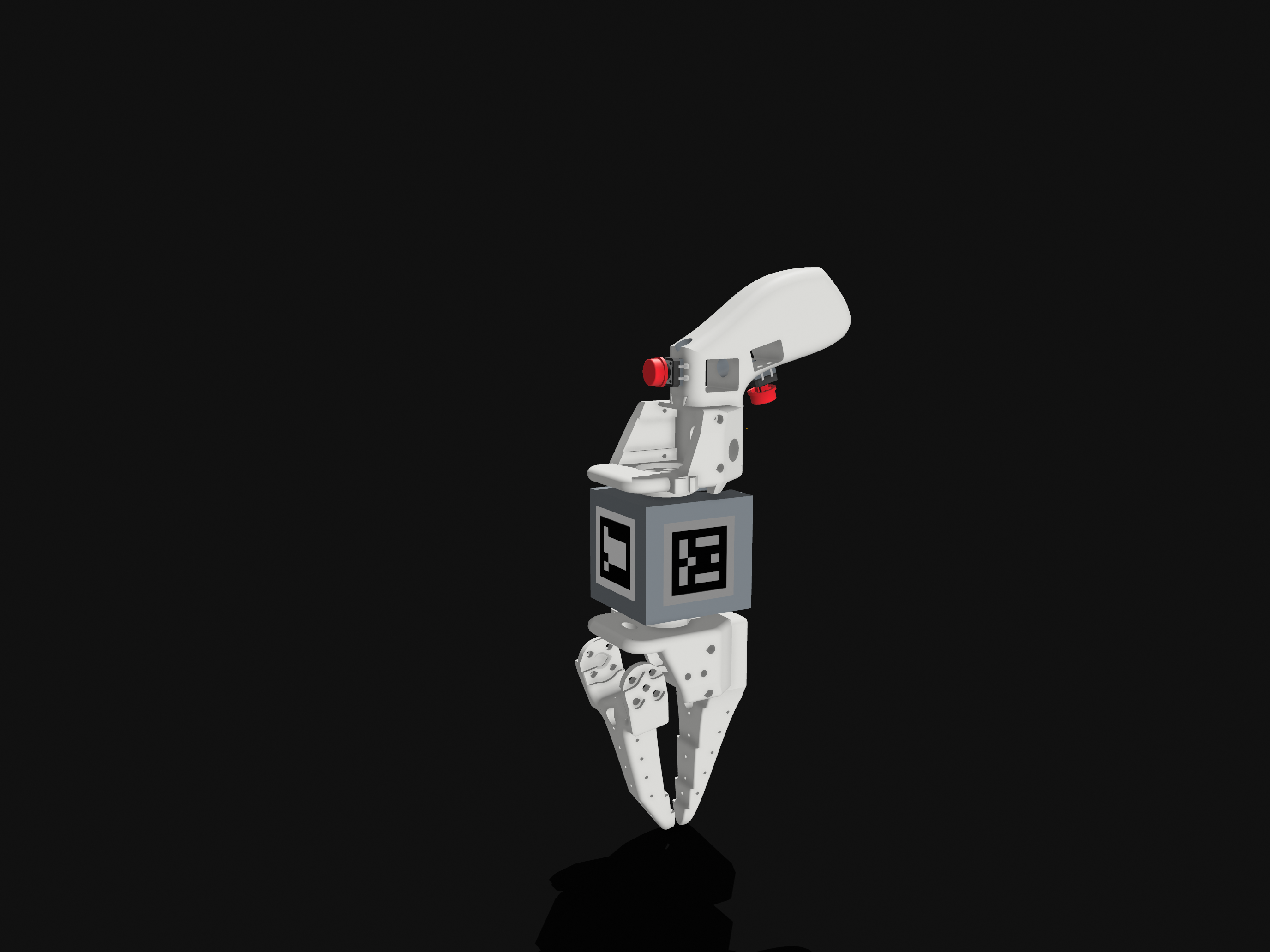
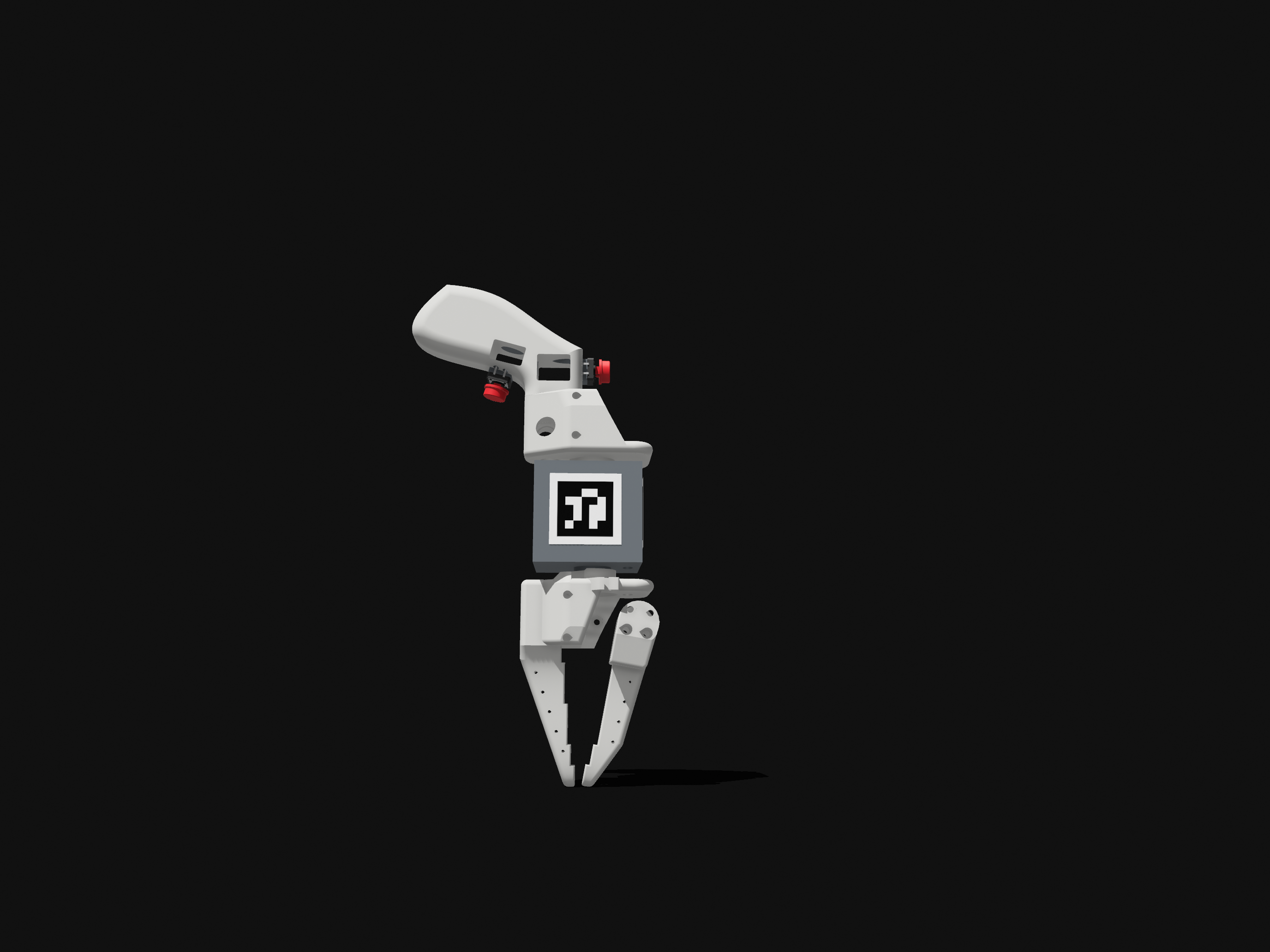
For collecting imitation learning data, I wanted something better than just moving the leader arms. This is a handheld teleoperation gripper inspired by Stanford’s UMI system, adapted for the LeRobot SO-101 platform and STS/SCS servo protocol.
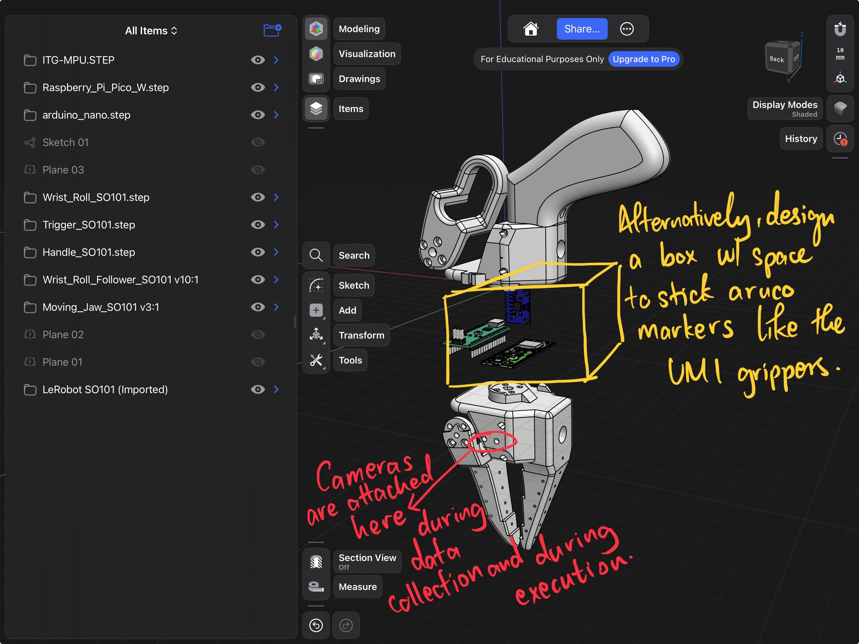
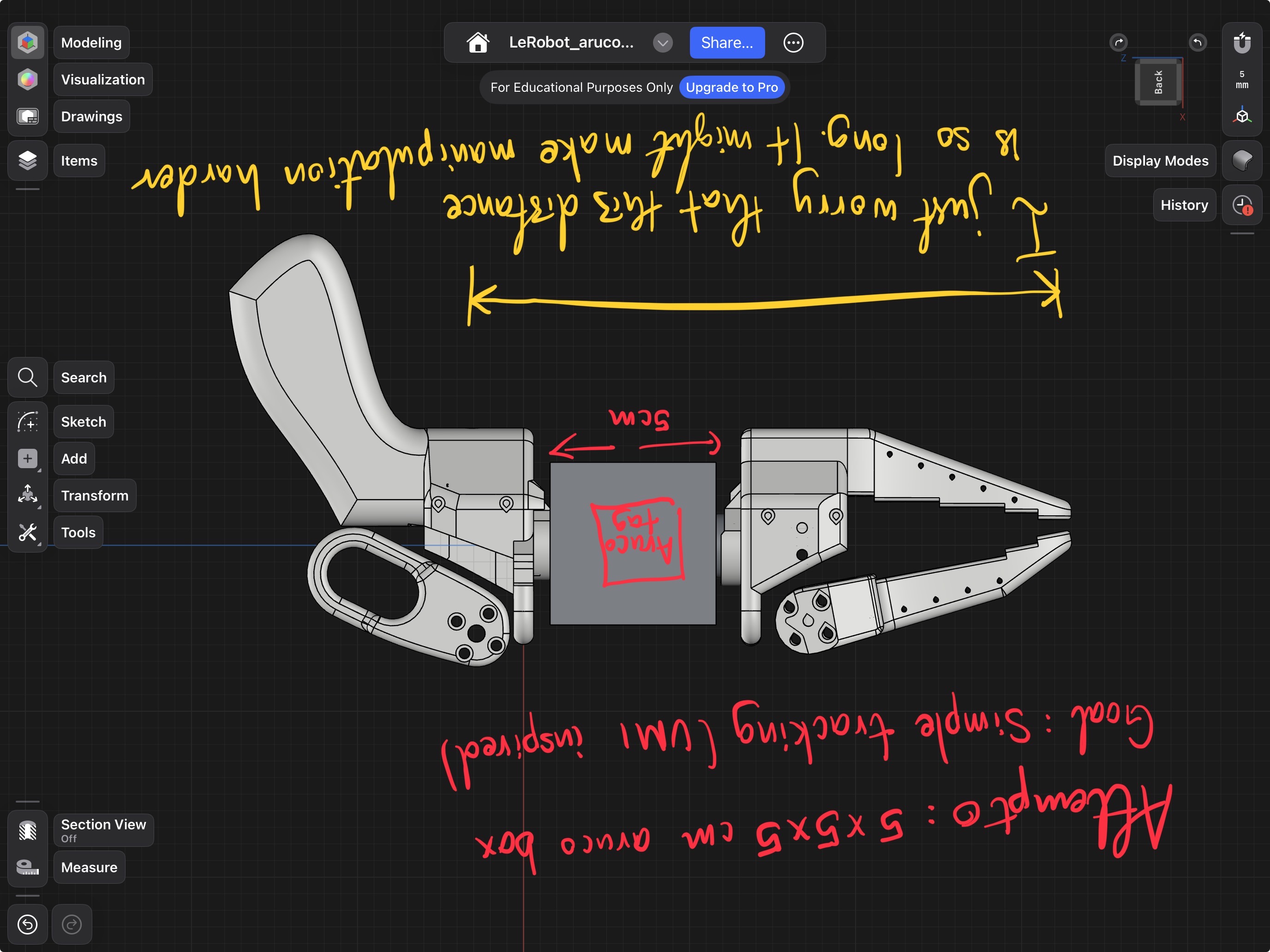
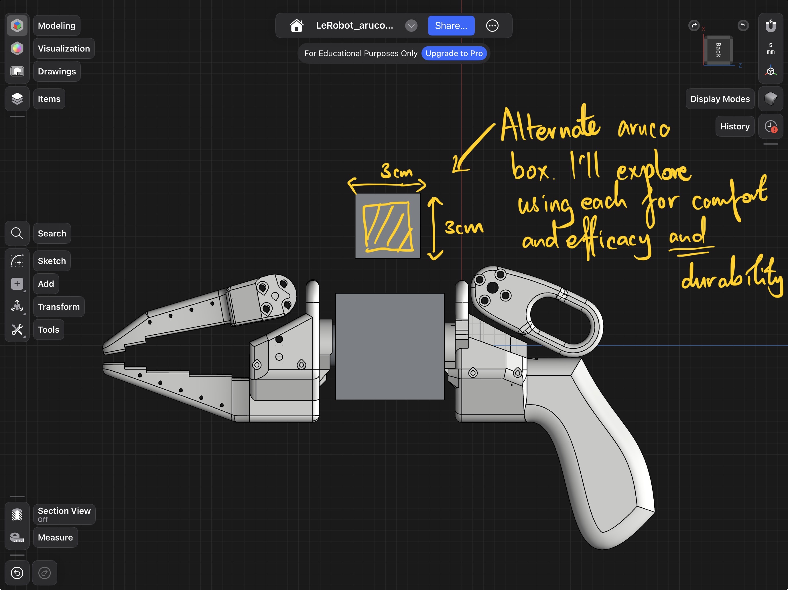
The design uses ArUco markers on a mounted box for camera-based pose estimation during data collection, plus an IMU for orientation, similar to how UMI tracks gripper pose without a wrist camera on the follower side.
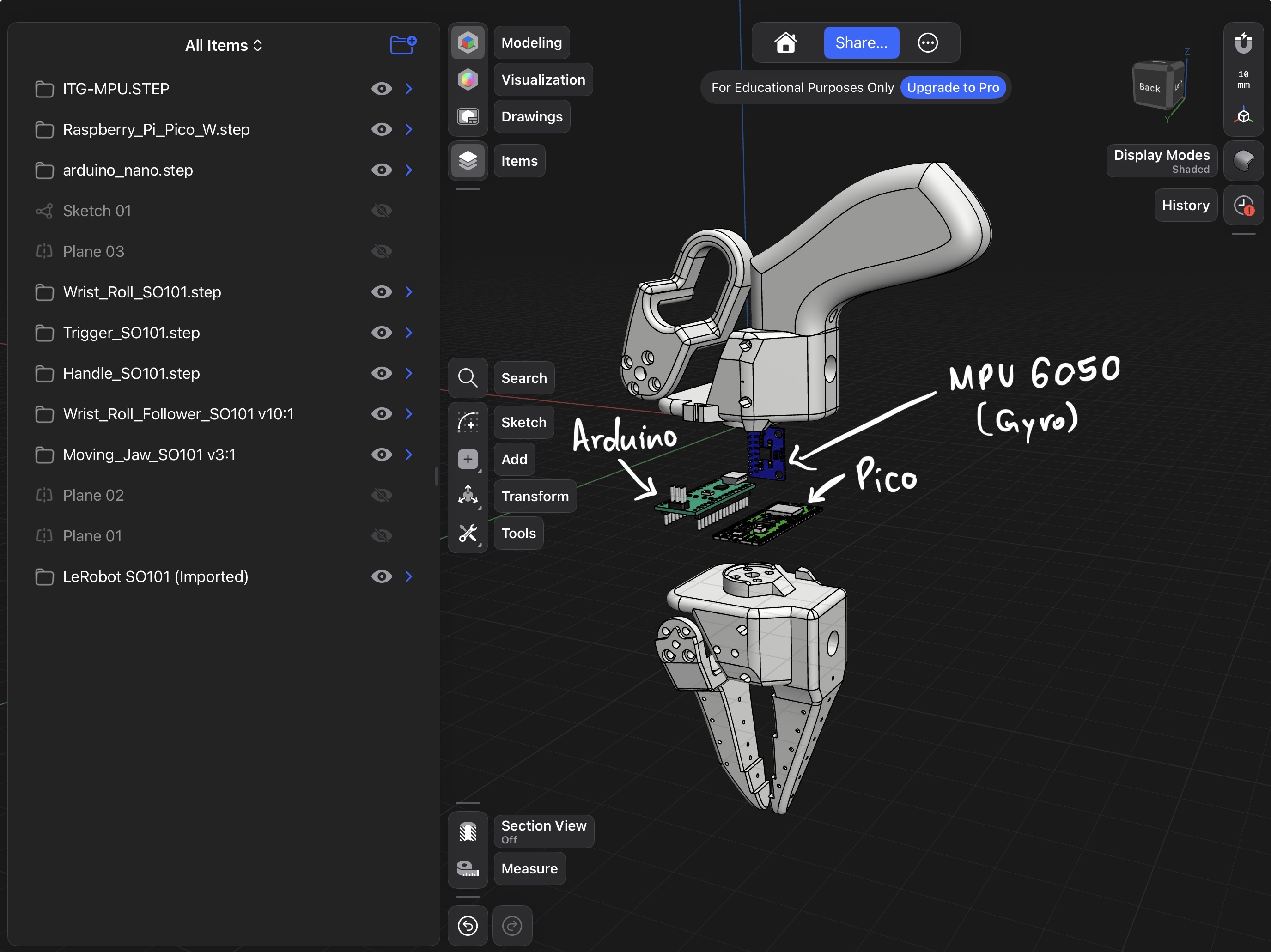
How it Works
- Operator holds the gripper and squeezes the trigger
- Trigger position read by potentiometer → Arduino → SO-101 controller over serial
- IMU tracks wrist orientation
- Same serial bus carries arm joint positions from the leader arm
- Synchronized at 30 Hz with multi-camera frames from the sew unit
Two gripper actuation approaches were prototyped. One version uses a thumb-actuated trigger (servo-based, serially communicating with the follower). The other (visible as the red buttons in the design iteration images) uses physical push buttons instead, removing the need for a second servo in the communication chain. Both approaches are compatible with the same ArUco tracking and IMU pipeline.
What’s Different from the Original UMI
| Original UMI | This Version | |
|---|---|---|
| Platform | Franka / UR5 | SO-101 / LeRobot |
| Communication | Dynamixel / ROS topics | STS/SCS half-duplex serial |
| Pose tracking | Wrist-mounted camera | ArUco + IMU |